Diferență între revizuiri ale paginii „Xilinx Platform Studio”
| Linia 31: | Linia 31: | ||
In the ''Cache'' window, click '''Next''' since there is no cacheable memory to configure in the system. | In the ''Cache'' window, click '''Next''' since there is no cacheable memory to configure in the system. | ||
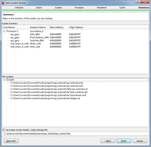
| − | In the ''Summary'' window, the wizard will display a summary of the configured system, including processors, peripheral names and their system addresses. Project file names are also shown along with their complete system paths. | + | In the ''Summary'' window, the wizard will display a summary of the configured system, including processors, peripheral names and their system addresses. Project file names are also shown along with their complete system paths. Click '''Finish''' when you are done reviewing your system configuration. |
[[Fișier:BSBWizard8.png|500px]] | [[Fișier:BSBWizard8.png|500px]] | ||
| + | |||
| + | The wizard will now proceed to generate all project files and load the project into the Platform Studio user interface. | ||
| + | |||
| + | == Platform Studio GUI == | ||
| + | |||
| + | The graphical user interface of Xilinx Platform Studio is split into three main panels. To the left there is the '''Navigator''' panel. Top-right and center are the '''System Assembly''' panel and the '''IP Catalog''' respectively. The bottom panel is the console window, along with warning and error tabs. | ||
| + | |||
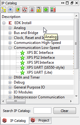
| + | The '''IP Catalog''' is a database of pre-designed peripherals and accelerator cores supplied by Xilinx as part of the ISE System Edition software package. Right-clicking on any item in the catalog will enable the user to add the item to the hardware system. The new system will need to be connected and mapped in the address space of the processor. | ||
| + | |||
| + | [[Fișier:IPCatalog.png]] | ||
| + | |||
| + | The '''System Assembly''' panel contains three tabs: '''Bus Interfaces''', '''Ports''' and '''Addresses'''. | ||
| + | |||
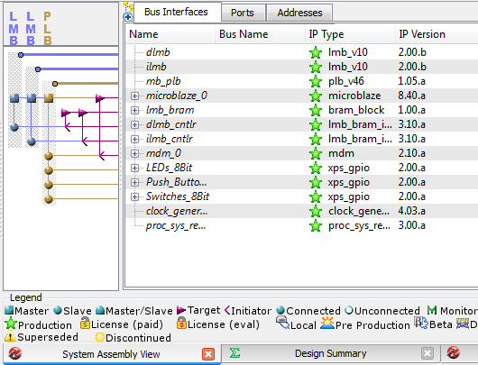
| + | The '''Bus Interfaces''' tab allows components to be connected and disconnected from system busses and the bus layout to be viewed in graphical form. | ||
| + | |||
| + | [[Fișier:XPSBusInterfaces.png]] | ||
| + | |||
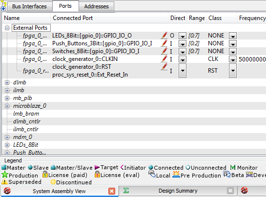
| + | The '''Ports''' tab allows connection of IO signals between components and FPGA pins, but can also be used to connect components with each-other or to connect global signals like clock and reset to individual system components. | ||
| + | |||
| + | [[Fișier:XPSPorts.png]] | ||
| + | |||
| + | The '''Addresses''' tab shows the processor address map split into regions corresponding to each peripheral. The amount of memory allocated to each peripheral is configurable. Peripheral address spaces can also be locked. | ||
| + | |||
| + | [[Fișier:XPSAddresses.png]] | ||
Versiunea de la data 16 noiembrie 2012 21:21
Xilinx Platform Studio enables its user to easily build hardware platforms based on the Microblaze soft processor and various development boards from Xilinx and other vendors. XPS is part of the Xilinx Embedded Development Kit (EDK), which itself is part of the Xilinx ISE Embedded and System Editions. For this tutorial, ISE 14.2 System Edition was used. The tutorial shows how to create a simple hardware system for the Digilent Nexys 2 board.
Getting Started
Start the Platform Studio, which will show a welcome menu with icons laid out in two columns: Getting Started and Documentation. From the Getting Started column, select the first option, Create New Project Using Base System Builder. This will start a wizard which will help the user configure and generate a hardware system.
Base System Builder
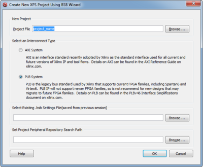
In the first window of the wizard, enter the name of your project. We will be using the project name xps_tutorial for the duration of this tutorial.
Next, select the interconnect type. AXI interconnects are generally used with ARM processors or newer FPGAs. Since we will be using a Microblaze processor on a Spartan-3 FPGA, select PLB and click OK.
In the Welcome window, select I would like to create a new design and click Next.
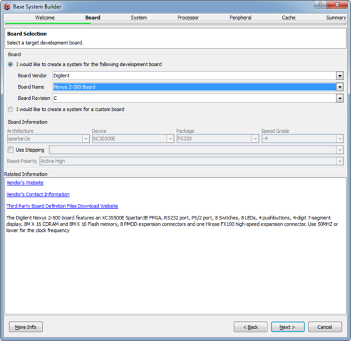
In the Board window, choose from the drop-down menus to build a system for the Nexys 2-500 board from Digilent. Information about the board, as well as links to the manufacturer, are available in the lower part of the wizard window.
In the System window, select to create a single-processor system.
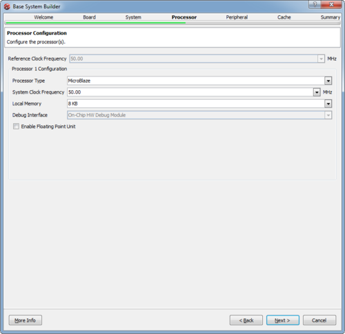
In the Processor window, select the Microblaze processor and 50 Mhz from the frequency drop-down menu. Change the Local Memory selection to 16KB or more from the default 8KB if you intend to implement more complex software projects on the hardware platform. Also, the user may choose to add hardware floating-point support to the Microblaze processor. For this tutorial, the local memory will be set at 16KB, and hardware floating-point will be disabled.
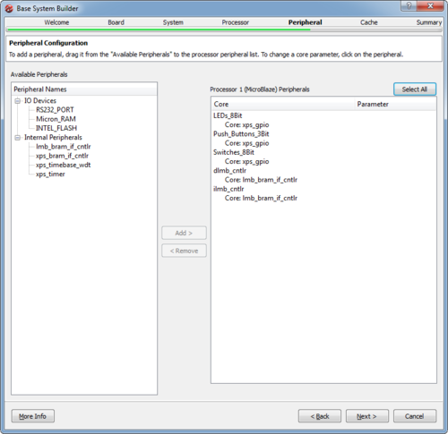
In the Peripheral window, remove the RS232_PORT, Micron_RAM and INTEL_FLASH peripherals. Notice that in the right panel the peripherals can be selected and certain parameters may be modified by the user.
In the Cache window, click Next since there is no cacheable memory to configure in the system.
In the Summary window, the wizard will display a summary of the configured system, including processors, peripheral names and their system addresses. Project file names are also shown along with their complete system paths. Click Finish when you are done reviewing your system configuration.
The wizard will now proceed to generate all project files and load the project into the Platform Studio user interface.
Platform Studio GUI
The graphical user interface of Xilinx Platform Studio is split into three main panels. To the left there is the Navigator panel. Top-right and center are the System Assembly panel and the IP Catalog respectively. The bottom panel is the console window, along with warning and error tabs.
The IP Catalog is a database of pre-designed peripherals and accelerator cores supplied by Xilinx as part of the ISE System Edition software package. Right-clicking on any item in the catalog will enable the user to add the item to the hardware system. The new system will need to be connected and mapped in the address space of the processor.
The System Assembly panel contains three tabs: Bus Interfaces, Ports and Addresses.
The Bus Interfaces tab allows components to be connected and disconnected from system busses and the bus layout to be viewed in graphical form.
The Ports tab allows connection of IO signals between components and FPGA pins, but can also be used to connect components with each-other or to connect global signals like clock and reset to individual system components.
The Addresses tab shows the processor address map split into regions corresponding to each peripheral. The amount of memory allocated to each peripheral is configurable. Peripheral address spaces can also be locked.
