Diferență între revizuiri ale paginii „Applications 10”
| (Nu s-au afișat 6 versiuni intermediare efectuate de același utilizator) | |||
| Linia 38: | Linia 38: | ||
=== cnt_bcd === | === cnt_bcd === | ||
| − | Whenever its ''' | + | Whenever its '''cen''' input is active, it increments or decrements, according to '''dir''' input. If '''dir''' is '''0''' it increments. If '''dir''' is '''1''' it decrements. |
| − | + | === fsm_cnt === | |
| − | === | ||
This automaton controls the sequence generated by '''cnt_bcd''', changing its direction of counting such that to keep the '''bcd''' sequence between the limits, '''limitl''' and '''limith'''. Whenever '''bcd''' value reaches one of the limits, the counting direction, '''dir''', is reversed. | This automaton controls the sequence generated by '''cnt_bcd''', changing its direction of counting such that to keep the '''bcd''' sequence between the limits, '''limitl''' and '''limith'''. Whenever '''bcd''' value reaches one of the limits, the counting direction, '''dir''', is reversed. | ||
| − | === | + | === fsm_ctrl === |
Another automaton controls the configuration process. It keeps two registers, '''limith''' and '''limitl''', whose values are changed according to the configuration protocol described above. At the reset, their values are set to the default ones, '''9''' and '''0'''. Two successive push update the values of the limits, after which the new limit values stay stable until reset. Keep in mind that the push button is active '''0''', and that a push is completed after the button is released. | Another automaton controls the configuration process. It keeps two registers, '''limith''' and '''limitl''', whose values are changed according to the configuration protocol described above. At the reset, their values are set to the default ones, '''9''' and '''0'''. Two successive push update the values of the limits, after which the new limit values stay stable until reset. Keep in mind that the push button is active '''0''', and that a push is completed after the button is released. | ||
| Linia 52: | Linia 51: | ||
=== rom16x8 === | === rom16x8 === | ||
| − | The ROM memory is a dual port read only memory. It | + | The ROM memory is a dual port read only memory. It may be initialized through the '''$readmemh''' or '''$readmemb''' tasks with proper values for digit display. Alternatively, the initialization of the memory content may be done with an '''init''' process: |
| + | <syntaxhighlight lang = "verilog"> | ||
| + | initial begin // the last 7 bits are the digit segment values | ||
| + | mem[0] = 8'b01000000; | ||
| + | mem[1] = 8'b01111001; | ||
| + | .... // initialization for the other memory locations | ||
| + | end | ||
| + | </syntaxhighlight> | ||
== Verification == | == Verification == | ||
| Linia 61: | Linia 67: | ||
* wait for 100 clock cycles | * wait for 100 clock cycles | ||
* set '''din''' and apply '''push''' for a couple of cycles | * set '''din''' and apply '''push''' for a couple of cycles | ||
| − | * change '''din''' to a | + | * change '''din''' to a high limit and apply '''push''' for a couple of cycles |
* let the simulation run for some other 100 clock cycles | * let the simulation run for some other 100 clock cycles | ||
| Linia 69: | Linia 75: | ||
defparam dut.pulsegen.CYCLE = 5; | defparam dut.pulsegen.CYCLE = 5; | ||
</syntaxhighlight> | </syntaxhighlight> | ||
| − | |||
== Implementation == | == Implementation == | ||
| Linia 79: | Linia 84: | ||
pulsegen(rst, clk, pulse) with an internal parameter named '''CYCLE''' | pulsegen(rst, clk, pulse) with an internal parameter named '''CYCLE''' | ||
| + | |||
cnt_bcd(rst, clk, cen, dir, value) | cnt_bcd(rst, clk, cen, dir, value) | ||
| + | |||
fsm_cnt(rst, clk, limith, limitl, value, dir) | fsm_cnt(rst, clk, limith, limitl, value, dir) | ||
| + | |||
fsm_ctrl(rst, clk, push, din, limith, limitl) | fsm_ctrl(rst, clk, push, din, limith, limitl) | ||
| + | |||
rom16x8(addra, douta, addrb, doutb) | rom16x8(addra, douta, addrb, doutb) | ||
| − | triangle(rst, clk, push, din, seg_din, seg_bcd) with the pulsegen instance name '''pulsegen''' | + | |
| + | triangle(rst, clk, push, din, seg_din, seg_bcd) with the pulsegen instance name '''pulsegen''' and a 4 bit connection named '''bcd''' | ||
| + | |||
triangle_tb with the triangle instance name '''dut''' | triangle_tb with the triangle instance name '''dut''' | ||
Versiunea curentă din 9 mai 2019 08:11
Requirement
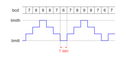
Design, verify and implement a triangular sequence generator. It generates a sequence of numbers that periodically increase and decrease between two configurable limits, limith and limitl. The sequence rate is one number per second. The binary sequence of numbers, bcd, is outputted for display as seg_bcd. Figure 1 shows an example of triangular sequence that varies between 6 and 9. The bottom waveform is the analog signal that would be generated by a DAC whose input is the bcd sequence.
Figure 1
The default limit values are 0 for limitl and 9 for limith, and they are set each time the reset is applied. To change the limits use the push button in this order. Set din to a desired value for the low limit and push the push button to set the limitl value to din value. Then change the din value to the desired high limit and with a second push set the limith value this new din value. The current din value is displayed through seg_din output. After configuration is done, the push button is ignored.
Description
triangle
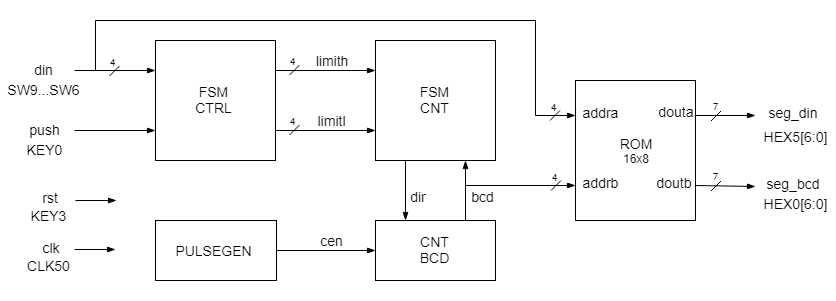
The top level design, named triangle, has 4 sequential blocks and one dual port ROM memory (Figure 2).
Figure 2
All sequential blocks are clocked by the same 50 MHz input clock and share the reset sinal, rst, active 0.
pulsegen
To easy the design of the circuit, the pulse generator, pulsegen, generates a periodic sequence of pulses, at a rate of one pulse per second, each pulse lasting only one clock cycle. The pulsegen is a counter that generates one pulse at each 50,000,000 clock cycles. However, to make possible the verification of the circuit, this number is not given as an explicit literal in HDL description but as a parameter declared inside the pulsegen module:
parameter CYCLE = 50000000;
The parameter value may be changed from the testbench to much lower values, suitable for verification (otherwise the simulation will run for hours to count 50 million pulses!).
The pulsegen output, pulse, is used to enable the counting of the cnt_bcd counter.
cnt_bcd
Whenever its cen input is active, it increments or decrements, according to dir input. If dir is 0 it increments. If dir is 1 it decrements.
fsm_cnt
This automaton controls the sequence generated by cnt_bcd, changing its direction of counting such that to keep the bcd sequence between the limits, limitl and limith. Whenever bcd value reaches one of the limits, the counting direction, dir, is reversed.
fsm_ctrl
Another automaton controls the configuration process. It keeps two registers, limith and limitl, whose values are changed according to the configuration protocol described above. At the reset, their values are set to the default ones, 9 and 0. Two successive push update the values of the limits, after which the new limit values stay stable until reset. Keep in mind that the push button is active 0, and that a push is completed after the button is released.
rom16x8
The ROM memory is a dual port read only memory. It may be initialized through the $readmemh or $readmemb tasks with proper values for digit display. Alternatively, the initialization of the memory content may be done with an init process:
initial begin // the last 7 bits are the digit segment values
    mem[0] = 8'b01000000;
    mem[1] = 8'b01111001;
    .... // initialization for the other memory locations
end
Verification
Write a testbench with the following test scenario:
- apply reset
- wait for 100 clock cycles
- set din and apply push for a couple of cycles
- change din to a high limit and apply push for a couple of cycles
- let the simulation run for some other 100 clock cycles
In the testbench module redefine the pulsegen parameter, such that is generates a pulse at each 5 clock cycles (instead of one at each 50,000,000 cycles):
defparam dut.pulsegen.CYCLE = 5;
Implementation
Using the recommended board display digits, push buttons, switches and clock sources (see Figure 1), implement the triangle top-level design module.
Interfaces
pulsegen(rst, clk, pulse) with an internal parameter named CYCLE
cnt_bcd(rst, clk, cen, dir, value)
fsm_cnt(rst, clk, limith, limitl, value, dir)
fsm_ctrl(rst, clk, push, din, limith, limitl)
rom16x8(addra, douta, addrb, doutb)
triangle(rst, clk, push, din, seg_din, seg_bcd) with the pulsegen instance name pulsegen and a 4 bit connection named bcd
triangle_tb with the triangle instance name dut

