Diferență între revizuiri ale paginii „Counter”
De la WikiLabs
Jump to navigationJump to searchCbira (discuție | contribuții) |
Cbira (discuție | contribuții) |
||
| (Nu s-au afișat 4 versiuni intermediare efectuate de același utilizator) | |||
| Linia 1: | Linia 1: | ||
| − | The | + | The counter is a sequential circuit that uses a register to generate a sequence of numbers. The simplest numerator generates a sequence of ascending consecutive numbers. The size of the counter is given by the number of bits of the registers used. |
| − | The | + | The schematic of this device is as follows: |
| − | [[File: | + | [[File: numarator.png | Block schematic of a counter]] |
| − | '''Note:' 'The count can be used as a frequency divider because each bit has a period twice as high as the previous one, and the bit 0 has a double period over the clock signal: | + | '''Note:''' The count can be used as a frequency divider because each bit has a period twice as high as the previous one, and the bit 0 has a double period over the clock signal: |
{| class="wikitable" | {| class="wikitable" | ||
| Linia 34: | Linia 34: | ||
* etc. | * etc. | ||
| − | == Implementing a | + | == Implementing a counter == |
As a sequential circuit, a counter is implemented exclusively with [[Verilog #Blocks always sequential. Non-blocking assignments | always sequential blocks]]. | As a sequential circuit, a counter is implemented exclusively with [[Verilog #Blocks always sequential. Non-blocking assignments | always sequential blocks]]. | ||
Versiunea curentă din 26 aprilie 2018 07:04
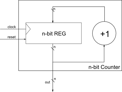
The counter is a sequential circuit that uses a register to generate a sequence of numbers. The simplest numerator generates a sequence of ascending consecutive numbers. The size of the counter is given by the number of bits of the registers used.
The schematic of this device is as follows:
Note: The count can be used as a frequency divider because each bit has a period twice as high as the previous one, and the bit 0 has a double period over the clock signal:
Interface of a counter
The interface of a numerator necessarily contains the following ports:
- Clock signal port;
- output signal port, which is even the counting register.
In addition, there may still be:
- Reset port;
- port that controls the counting direction;
- port that stops or starts counting;
- port giving the maximum value the numerator can reach;
- port that commands to load a start value in the counter of the counter and the port on which this value is given;
- etc.
Implementing a counter
As a sequential circuit, a counter is implemented exclusively with always sequential blocks.
