Diferență între revizuiri ale paginii „Applications 4”
| Linia 28: | Linia 28: | ||
[[Fișier: letters.png]] | [[Fișier: letters.png]] | ||
| + | |||
| + | # create a new project in a new folder | ||
| + | # create a new source file for the top-level module | ||
| + | # create a new source file for the adder. The adder is described behaviorally using a continuous assignment. | ||
| + | # copy from the folder of Exercise 1 the source file of the transcoder module into the folder of this project. Add the file to the project. | ||
| + | # the top-level module has a structural description. It contains only the instances of the adder and of the transcoder. | ||
| + | # assign switches SW[9], SW[8] and SW[7] for the input '''a''', SW[2], SW[1] and SW[0] for the input '''b''', and Digit0 pins for the output '''seg''' | ||
| + | # implement and check that the result of adding two 3 bit numbers is correctly displayed on Digit0 (in hexadecimal) | ||
== Exercise 3 == | == Exercise 3 == | ||
Versiunea de la data 13 martie 2019 19:45
Exercise 1
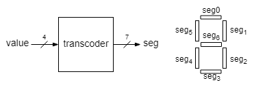
Make a 7-segment display transcoder using a case block that displays values from 0 to 9. The input of the module will be called value and the output seg.
The output bits would control the segments of a digit display, one bit for each segment. The segment is lit when the corresponding bit is 0, otherwise it is off (negative logic).
For all numbers greater than 9 the digit must be off. All these 6 cases may be covered in a single assignment under the default case.
Open the transcoder VPL activity on Moodle, upload the source file of the transcoder, run the test and check the results. In case of errors fix the design and retry. After you get TEST PASS on Moodle, proceed to implementation.
Test the transcoder by connecting its 4 bit input to SW[3], SW[2], SW[1] and SW[0], and displaying the output on a 7-segment display, the right digit (Digit0) of DE1-SOC display.
Coding style:
- case statements should always include the default case.
Exercise 2
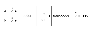
Implement a 3 bit adder whose result is displayed as a hexadecimal digit.
The result of the 3 bit addition is in the range [0, ... ,14] and it may be written in the hexadecimal base using only one digit. The transcoder must be extended to show hexadecimal digits greater than 9. Use the most common 7-segment symbols for them:
- create a new project in a new folder
- create a new source file for the top-level module
- create a new source file for the adder. The adder is described behaviorally using a continuous assignment.
- copy from the folder of Exercise 1 the source file of the transcoder module into the folder of this project. Add the file to the project.
- the top-level module has a structural description. It contains only the instances of the adder and of the transcoder.
- assign switches SW[9], SW[8] and SW[7] for the input a, SW[2], SW[1] and SW[0] for the input b, and Digit0 pins for the output seg
- implement and check that the result of adding two 3 bit numbers is correctly displayed on Digit0 (in hexadecimal)
Exercise 3
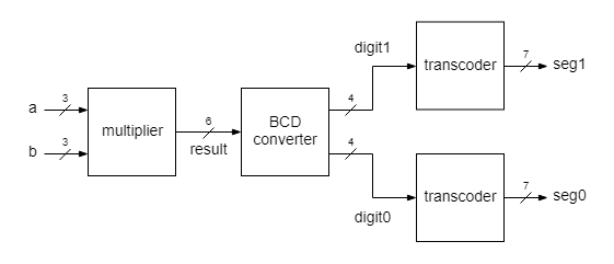
Implement a 3 x 3 bits multiplier, with the result shown in decimal base as a 2 digits number.
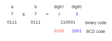
This project comprises a top module with 4 blocks. The first block, multiplier, takes in two 3 bit numbers, a and b, and delivers the result of their multiplication in binary format. The input operands and the result are treated as unsigned integers (natural numbers). The next block, BCD converter, converts the result from the binary format to the decimal. The decimal digits are coded in binary, therefore a multidigit number is coded in the so called BCD format (Binary-coded decimal), where each decimal digit is represented as a 4 bit number.


