Diferență între revizuiri ale paginii „DIC Seminar 1”
Cbira (discuție | contribuții) |
Cbira (discuție | contribuții) |
||
| Linia 24: | Linia 24: | ||
<syntaxhighlight lang = "verilog"> | <syntaxhighlight lang = "verilog"> | ||
and node_name (output, input_1, input_2, ...) entry_n); | and node_name (output, input_1, input_2, ...) entry_n); | ||
| − | </ | + | </syntaxhighlight> |
| Linia 44: | Linia 44: | ||
// Then give the functional or structural details | // Then give the functional or structural details | ||
endmodule | endmodule | ||
| − | </ | + | </syntaxhighlight> |
== Exercise 3 == | == Exercise 3 == | ||
| Linia 82: | Linia 82: | ||
circuit2 doru (.in3 (w), .in4 (b), .out (c)); | circuit2 doru (.in3 (w), .in4 (b), .out (c)); | ||
circuit3 zuzu (.in0 (en), .in1 (c), .out (out)); | circuit3 zuzu (.in0 (en), .in1 (c), .out (out)); | ||
| − | </ | + | </syntaxhighlight> |
... where modules have ports declared as follows: | ... where modules have ports declared as follows: | ||
| Linia 110: | Linia 110: | ||
... | ... | ||
endmodule | endmodule | ||
| − | </ | + | </syntaxhighlight> |
== The main concepts of Verilog introduced in this seminar == | == The main concepts of Verilog introduced in this seminar == | ||
| Linia 123: | Linia 123: | ||
...... then give the functional or structural details | ...... then give the functional or structural details | ||
endmodule | endmodule | ||
| − | </ | + | </syntaxhighlight> |
2. The ports of a circuit can be declared | 2. The ports of a circuit can be declared | ||
| Linia 137: | Linia 137: | ||
..... | ..... | ||
endmodule | endmodule | ||
| − | </ | + | </syntaxhighlight> |
<u> Option 2 (Verilog 2001) </u> | <u> Option 2 (Verilog 2001) </u> | ||
| Linia 148: | Linia 148: | ||
... | ... | ||
endmodule | endmodule | ||
| − | </ | + | </syntaxhighlight> |
If we have several similar entries we can also write: | If we have several similar entries we can also write: | ||
| Linia 157: | Linia 157: | ||
... | ... | ||
endmodule | endmodule | ||
| − | </ | + | </syntaxhighlight> |
3. '' 'The code lines in Verilog end with'; '' '' (there are exceptions that we will explicitly mention, for example after the last line - '' endmodule '' above. ; "Causes an action). | 3. '' 'The code lines in Verilog end with'; '' '' (there are exceptions that we will explicitly mention, for example after the last line - '' endmodule '' above. ; "Causes an action). | ||
| Linia 178: | Linia 178: | ||
<syntaxhighlight lang = "verilog"> | <syntaxhighlight lang = "verilog"> | ||
ex1 UUT (port list); | ex1 UUT (port list); | ||
| − | </ | + | </syntaxhighlight> |
Ports can be connected according to their order or by explicitly defining the signals connected to each port: | Ports can be connected according to their order or by explicitly defining the signals connected to each port: | ||
| Linia 185: | Linia 185: | ||
ex1 dut1 (i0, i1, i2, out); | ex1 dut1 (i0, i1, i2, out); | ||
ex1 dut1 (.a (i0), .b (i1), .s (i2), y (out)); | ex1 dut1 (.a (i0), .b (i1), .s (i2), y (out)); | ||
| − | </ | + | </syntaxhighlight> |
Although in version 2 we can write the ports in any order, we prefer to write them in the same order! | Although in version 2 we can write the ports in any order, we prefer to write them in the same order! | ||
| Linia 199: | Linia 199: | ||
and P1 (out1, in1, in2, ..., ink); // for all logic gates predefined in verilog the first port is the output | and P1 (out1, in1, in2, ..., ink); // for all logic gates predefined in verilog the first port is the output | ||
and P2 (out2, in1, in2); // Each instance must have a unique name | and P2 (out2, in1, in2); // Each instance must have a unique name | ||
| − | </ | + | </syntaxhighlight> |
The other logical gates are: 'nand', '' or '', '' nor '', '' xor '', '' xnor ''. | The other logical gates are: 'nand', '' or '', '' nor '', '' xor '', '' xnor ''. | ||
Versiunea de la data 29 martie 2018 08:34
In this seminar you will learn to describe some simple digital circuits in Verilog language and use the Quartus II and ModelSim programs.
'Keywords:' logical gates, ports, waveform, project, mode, instantiation, testbench
Verilog syntax: 'module' ',' 'wire' ',' 'reg' ',' 'initial' ',' 'stop' '
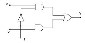
Verilog is a hardware description language. In this language we can describe digital circuits as in Figure 1.
Notions and Knowledge Required
- Boolean Logic and Numerical Systems
- Syntax notions Verilog
Exercise 1
Figure 1 is a schematic diagram of a digital circuit containing logical gates. Describe this schema in Verilog.
'Explanations' : The elementary logic gates are predefined in Verilog: 'not' , 'and' , 'nand' 'nor' , 'xor' , 'nxor' . The correct syntax is, for instantiating a 'and' gate:
and node_name (output, input_1, input_2, ...) entry_n);
Exercise 2
Create a Verilog file describing the circuit from exercise 1.
Explanations: The description of a circuit includes:
- interface (input and output ports declaration)
- description of the function or circuit diagram
In Verilog, circuit descriptions are made up of modules. The syntax is the following:
module_meu (port_port) module; / * ports are external circuit connections * /

// first report ports
// Then give the functional or structural details
endmodule
Exercise 3
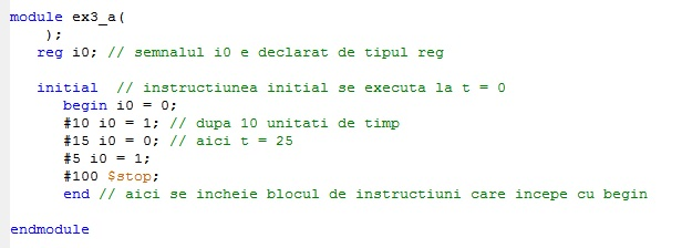
Generate the waveforms in the following figures in the simulator.
1. Signal i0:
2. Two signals, i0 and i1:
Three signals:
Resolve Item 1: </ u>
It will write a new source file that has no external ports (because it does not describe a circuit).
Example 4
Simulate the operation of the module from exercise 2 by applying the signals from exercise 3 - point 3. Knowing that this circuit is a multiplexer (circuit selection), analyze the waveforms to see if they are correct. Modify the waveform at input s and check the correct operation.
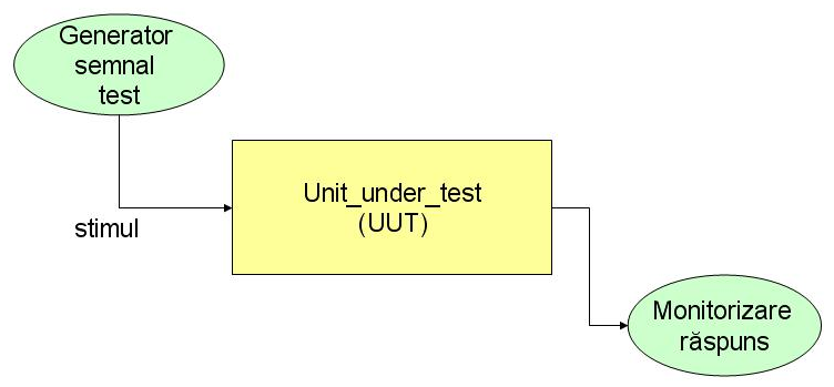
'Explanation:' To simulate the operation of a circuit, we need to build a testbench described in a new module. We apply the respective signals to the input of the tested circuit - we instantiate that circuit. We simulate the test module and then analyze the waveforms to see if they correspond to the implemented function.
Exercise 5
Draw the schema described by the following Verilog code:
circuit1 ana (.in1 (a), .in2 (b), .out1 (w), .out2 (en));
circuit2 doru (.in3 (w), .in4 (b), .out (c));
circuit3 zuzu (.in0 (en), .in1 (c), .out (out));
... where modules have ports declared as follows:
module circuit1 (
            input in1, in2,
            output out1,
            output out2);
...
endmodule


module circuit2 (
            input in3, in4,
            output out);
...
endmodule


module circuit3 (
            input in1,
            input in0,
            output out);
...
endmodule
The main concepts of Verilog introduced in this seminar
1. 'Circuit descriptions in Verilog are made up of' 'modules. Any module starts with the module word and ends with endmodules. Modules can not overlap and can not be included in each other.
module_meu (port_port) module; / * ports are external circuit connections * /

...... // first report ports
...... then give the functional or structural details
endmodule
2. The ports of a circuit can be declared
- in the module body
- Compact in the port list.
Entries to Verilog are declared with the word input , outputs are output .
Version 1 (Verilog '95)
module circuit (a, b, c, out);
   input a, b, c; // we can put more on the same line, separated by,
   output out;
.....
endmodule
Option 2 (Verilog 2001)
module circuit (
input a, // write with tabs to be visible
input b,
input c,
output out);
...
endmodule
If we have several similar entries we can also write:
module circuit (
input a, b, c,
output out);
...
endmodule
3. 'The code lines in Verilog end with'; (there are exceptions that we will explicitly mention, for example after the last line - endmodule above. ; "Causes an action).
4. 'The comments' are entered with // or with /****/, they will appear in the editor of the program with another color and are ignored in simulation and synthesis.
5. 'Simulation of circuit operation'
To verify the correct operation of a circuit, we need to apply input signals to it and verify that the output is the way we expected it to be, ie, simulating it.
We define a circuit that is actually a testbench (testbench)
This circuit is a distinct, special test module, usually called test mode. The test module does not have external connections, but it instantiates the module that we test (UUT) and we have previously described it in another file.
6. 'The instantiation' allows the use of a module after it has been defined. Once we have defined a module, its name is similar to a Verilog instruction. For example, after defining the circuit of exercises 1 and 2, we can use it in other schemes as follows:
ex1 UUT (port list);
Ports can be connected according to their order or by explicitly defining the signals connected to each port:
ex1 dut1 (i0, i1, i2, out);
ex1 dut1 (.a (i0), .b (i1), .s (i2), y (out));
Although in version 2 we can write the ports in any order, we prefer to write them in the same order! We may not connect signals to all inputs if they are not needed in a particular context. The instantiated module must be defined in the same project (not necessarily in the same file).
7. Logical gates in Verilog
In Verilog, elementary logic gates are pre-defined as primitive, so there are special words of language.
For the AND function:
and P1 (out1, in1, in2, ..., ink); // for all logic gates predefined in verilog the first port is the output
and P2 (out2, in1, in2); // Each instance must have a unique name
The other logical gates are: 'nand', or , nor , xor , xnor . At all of these gates, the default is first and exit can be as many as possible.
'Note' : The simple notes used for logical functions in the current script are not identical to the Verilog operator symbols.
| Logical function | Symbol | operator Verilog | - | AND | (can be omitted) | & | - | OR | + | </ nowiki> | - | XOR | & Oplus; | ^ | - | NOT | ' | ~ |
|---|
Rules of Good Practice
Organization of Files
- Save the modules you write into separate files.
- The name of the file is the same as the module name.
- For simulation, use a distinct folder.
Writing code
- Give suggestive names to modules, ports and signals.
- Enter comments to document the code.
- Use tabs and blank lines to align and group instruction blocks.


