Introduction. Verilog HDL (Verilog syntax)
Introduction to Digital Circuits
Analog Signals
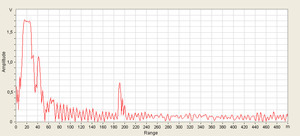
Starting with electro-kinetics lessons from high school physics classes (voltage sources, resistors, capacitors, coils, etc.) and ending with Electronic Devices and Circuits, the studied systems were made up of analogue circuit components . Analog circuits are circuits in which the studied quantities (current, voltage) vary continuously at certain intervals. A concrete example is an audio amplifier that picks up an analog audio signal and amplifies it to be transmitted further to a speaker system. You can see an example of an analog signal in the figure below. Of course, this image is generated by a computer, which is a digital device, so it can not represent a true analog signal but can only simulate such a signal with some precision.
Digital Signals
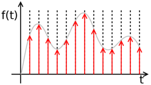
A digital signal is a set of discrete values, each of these values being part of a discrete set of rational values. Transforming an analog signal into a digital signal implies a loss of precision. Let's take for example a simple sinusoidal analog signal, representing the time variation of the voltage at the terminals of a resistor. Between the moments t=0 and t=1, the function, being continuous, has an infinity of values, so it is impossible to isolate each value, the sequence thus obtained being infinite. The procedure, in this situation, is to isolate only some of the values, at certain times, called samples, so that we get a finite set of values. This procedure is called sampling and the time period between two successive samples is called the sampling period. The shorter the sampling period (or the higher sampling frequency), the better the digital signal is a more accurate copy (lower precision loss) than the original analog signal. If, however, the analog signal is limited bandwidth (ie it can be written as a finite sum of sinusoidal signals), then sampling theorem shows that if the sampling is done at a frequency at least twice as high as the maximum frequency of the signal spectrum, of the sample series can be obtained with 100% accuracy of the original analog signal.
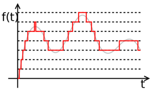
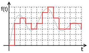
However, there is still a problem. The signal being continuous, the sample values are in a continuous space, therefore of infinite precision. To reduce the accuracy of values, use a method called quantization. This process involves dividing the range of possible signal values into subdivisions. The more subtle these subdivisions, the higher the values obtained by the quantization will be closer to the real values of the original signal, but will be represented by a more number of symbols.
In conclusion, a digital signal is a sequence of numbers obtained by sampling and quantization of an analog signal.
Numbers and symbols. Numbering Bases
As noted in the previous chapter, a digital signal is a string of values. These values are represented by symbols, belonging to a numbering base. The simplest example is the one we are all accustomed to, that is, the decimal point, using the figures from 0 to 9 as symbols. But this is by no means the only one. Other examples would be the Roman numeration system where symbols I, V, X, L, C, D, and M are used as symbols, where the value of these symbols in a number depends on their order. The same can be said about the decimal numbering base where, for example, the symbol 9 has another value if it is in the first position (9) than if it is on the second (90). What is interesting to note is that, despite the mental association between the symbols we have been used to working with and the numerical values they express, the two notions are completely distinct. The value "ten" can be expressed numerically in the decimal number as 10 in the Roman numeration system as X in the hexadecimal system as A in the binary system as 1010 in the octal as 12 but all these representations actually express the same number.
Binary numbering system
As the name says, this system uses only two symbols, most of them being 0 and 1. Therefore, a number can be represented in the binary system (also called base 2) as a sequence of 0 and 1 The order of the symbols in a written number in the second base follows the same rules as the numbers written in the decimal. Thus, if in a decimal number, the number 7 in position 4 was equivalent to 7 * 10 4 , where 10 is equal to the number of distinct symbols used, then to base 2, 4 is equivalent to 1 * 2 4 . This is also the rule for converting the numbers from base 2 to base 10. Therefore:
1001010 (2) =1 * 2 6 + 0 * 2 3 + 0 * 2 2 0 + 8 + 0 + 2 + 0=54 (10)
Transforming a number from the decimal to the binary involves the repeated division into 2 (the number of base symbols), where the split at each iteration is given by the previous division. The operation is repeated as long as it is different than 0. The binary number is given by the remainder sequence from the last division to the first.
The advantage of the binary system is that the reduced number of symbols makes the number of possible operations between two random symbols reduced, so it is easy to imagine a physical realization of some circuits to implement these operations. The disadvantage is that for relatively small numbers, many symbols are needed for representation. Therefore, for the flexibility of the operation with values represented by many symbols, the hexadecimal numbering base is used, ie the base 16. As the name says, the hexadecimal base uses 16 symbols: the digits 0 to 9, and the characters a, b, c d, e and f. The use of base 16 is advantageous due to the very slight passage between it and base 2. Thus, at any value represented by a sequence of four binary symbols, one and only one hexadecimal symbol corresponds.
Computation and control
We have therefore come to the conclusion that calculations can be made using only two symbols corresponding to zero and one. We have a numbering base (base two) that can be used to make the most complex calculations with the same accuracy as the decimal ones. But besides the actual calculation, a computer system must be able to make decisions, that is to say, to evaluate an expression and decide its value of truth, a general type of operation 'if' else . The simplest example of a function that can not be calculated without making a decision is the function function (in fact, any function with branches). This is of the form: <syntaxhighlight lang="Pascal"> if (operand <0) then (result=-operand) else (result=operand); <syntaxhighlight>
The expression (operand <0) is what is called a logical expression. Logical phrases in Boolean algebra can only take two values: true or false'. These values can be denoted by the same symbols that we use for numerical values in the second base, ie ' 0 for false value and ''''''For truth value true (true) .
How numeric operators can be applied to numerical operators (addition, subtraction, multiplication) and logical values can be applied to logical operators (AND, OR, NOT, OR EXCLUSIVELY). These are explained in detail on the Wikipedia page of the boolean algebra.
The conclusion is that using the same two symbols, we can do calculations using binary algebra, but we can exercise control over a function using boolean algebra. As the symbols overlap for computation and control, the associated operators may have the same form, and then the distinction is made only by their interpretation. For example, the result table for multiplying two two-digit numbers (numerical operation) looks like this:
| - bgcolor="#ddeeff" align="center" | INPUT | OUTPUT | - bgcolor="#ddeeff" align="center" | A | B | A * B | - bgcolor="#ddffdd" align="center" | 0 | 0 | 0 | - bgcolor="#ddffdd" align="center" | 0 | 1 | 0 | - bgcolor="#ddffdd" align="center" | 1 | 0 | 0 | - bgcolor="#ddffdd" align="center" | 1 | 1 | 1 | |
At the same time, the logical AND operation which returns 1 if and only if both operands are 1 (I go to film IF it does not rain AND I have money), has the following table of truth:
| - bgcolor="#ddeeff" align="center" | INPUT | OUTPUT | - bgcolor="#ddeeff" align="center" | A | B | A AND B | - bgcolor="#ddffdd" align="center" | 0 | 0 | 0 | - bgcolor="#ddffdd" align="center" | 0 | 1 | 0 | - bgcolor="#ddffdd" align="center" | 1 | 0 | 0 | - bgcolor="#ddffdd" align="center" | 1 | 1 | 1 | |
It is noted that the two functions are identical. In this way, the distinction between logical value and numerical value (logical operator and numeric operator) is the interpretation of the input values (if these are logical or numerical values) and the implementation of the operators is identical (therefore the associated circuit is identical).
Circuits
In digital electronics, as a matter of fact in the whole branch of digital circuitry (ie computers) technology as well as in the information terrain, an element that can take a binary value associated with a binary symbol is called [http: //en.wikipedia. org /wiki /Bit bit]. The basis of digital circuits, however complex, is given by the sub-circuits that compute the single and binary operations (i.e., which have one or two operands) between two bits. Such a sub-circuit is called gate (en: gate). The same gateway can be considered the implementation of a one-bit numeric operator, but also the implementation of a logical operator.
The way to encode the values associated with binary symbols in digital electronics is through a potential difference between two points. In the current technology used (CMOS), a voltage between 0 and Vdd /2 is associated with the binary value of 0 and a voltage between Vdd /2 and Vdd of the binary value of 1 . [1]
The simplest gate is the one that implements the denial logic operation (it has a single input and a single output that is always different from the input, ie for input 0, output is 1 and for input 1, the output is 0). This gate is called inverse, or bears NO (NOT: http://en.wikipedia.org/wiki/Inverter_(logic_gate) inverter, NOT gate).
Symbols and truth tables for the most-used gates:
As with the symbolic representation of the operational amplifiers, it is noticed that neither the logic gates were represented by the power ports (Vdd and Vss), visible on the CMOS inverter schema. They are implicitly connected to the power supply, respectively to the mains.
Verilog HDL
At present, a digital circuit can reach up to 1 billion gates. This implies that we need tools to automate the design process. This can be done using hardware description languages (Hardware Description Languages). These languages are specially designed to describe a digital circuit, either in terms of behavior or in terms of structure. Clearly, a behavioral description of a circuit will be more succinct, but will not provide information about the desired structure (gate-level), while a structural description will be more accurate in terms of circuit components, but more long and perhaps more difficult to understand.
There are two very popular hardware description languages: Verilog and VHDL. In the continuation of this Digital Integrated Circuits Lab, we will use the Verilog language for circuit descriptions. Its syntax is simple and is partly inherited from C. However, it is very important to note that Verilog is not a programming language. It does not "run" sequentially by a processor, it synthesizes in a circuit or simulates it. Therefore, Verilog users need to decipher to think sequentially as if each line of code is running after the previous one, and rather they have to imagine how the circuit that that code describes. Thus, the most interesting difference with a programming language is that the order of the code blocks in a module does not matter.
Before you start working with some simulation and synthesis software, go through the tutorial explaining the syntax [[Verilog]


