Applications 4
Exercise 1
Caesar cipher
The Caesar cipher is the simplest substitution cipher. A plain text message is encrypted by replacing each letter from the message by another one that is some fixed number of positions down the alphabet. All letters of the alphabet are changed using the same fixed number of positions. The letters are “shifted” down the alphabet, this code being also named shift cipher. In this exercise and the following ones, we assume that the plain and encoded messages contain only ASCII uppercase letters A to Z, without blank spaces between words. The encryption is done such that A-Z set of letters are translated to letters from the same set A-Z. For example, if the shift is of 3 positions down the alphabet, A translates to D, B to E, C to F, a.s.o. To achieve the circularity of the encoding, W translates to Z, X to A, Y to B and Z to C.
ASCII code
The ASCII code is the widest used character encoding standard in digital technology. Originally limited to 7 bits it usually uses 8 bits to code for the latin alphabet letters, uppercase and lowercase, digits, punctuation marks, some special symbols, and some commands. We need to know the ASCII codes for the uppercase letters of the alphabet:
| Letter | A | B | C | D | E | F | G | H | I | J | K | L | M | N | O | P | Q | R | S | T | U | V | W | X | Y | Z |
| hex code | 41 | 42 | 43 | 44 | 45 | 46 | 47 | 48 | 49 | 4a | 4b | 4c | 4d | 4e | 4f | 50 | 51 | 52 | 53 | 54 | 55 | 56 | 57 | 58 | 59 | 5a |
Caesar coder
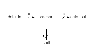
Your goal is to design a configurable Caesar encoder, where the shift is set from the outside. The circuit receives an ASCII letter on data_in input, shifts it by a number of positions given by the key input and outputs the resulting letter as data_out. It is supposed that the input data are restricted to the A-Z ASCII codes and the shift is an unsigned integer no greater than 26 (the length of the alphabet)
The implementation adds the shift number to the ASCII code of the input letter and corrects the sum such that the output ASCII code is also in the A-Z range of ASCII codes.
assign data_out = data_in + shift > 8'd90 ?
                  data_in + shift - 8'd26 :
                  data_in + shift;
Exercise 1
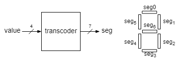
Make a 7-segment display transcoder using a case block that displays values from 0 to 9. The input of the module will be called value and the output seg.
The output bits would control the segments of a digit display, one bit for each segment. The segment is lit when the corresponding bit is 0, otherwise it is off (negative logic).
For all numbers greater than 9 the digit must be off. All these 6 cases may be covered in a single assignment under the default case.
Because seg values are easier to handle in binary, the assigned values for seg should be given as binary constants. A number in binary format (or a combination of bit values) must be preceded by the base specificator, 'b, according to the template numberOfBits'bvalue as in the following examples:
8'b11 |
3, in binary format on 8 bits |
8'b00000011 |
3, in binary format on 8 bits. Leading zeros are explicitly written |
8'b0000_0011 |
when there are too many bits, the underline, _ may be used to split bits into smaller groups |
Open the transcoder VPL activity on Moodle, upload the source file of the transcoder, run the test and check the results. In case of errors fix the design and retry. After you get TEST PASS on Moodle, proceed to implementation.
Test the transcoder by connecting its 4 bit input to SW[3], SW[2], SW[1] and SW[0], and displaying the output on a 7-segment display, the right digit (Digit0) of DE1-SOC display.
Coding style:
- case statements should always include the default case.
Exercise 2
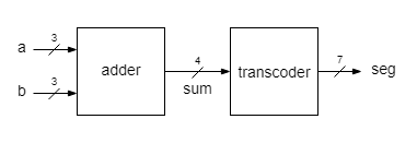
Implement a 3 bit adder whose result is displayed as a hexadecimal digit.
The result of the 3 bit addition is in the range [0, ... ,14] and it may be written in the hexadecimal base using only one digit. The transcoder must be extended to show hexadecimal digits greater than 9. Use the most common 7-segment symbols for them:
- create a new project in a new folder
- create a new source file for the top-level module
- create a new source file for the adder. The adder is described behaviorally using a continuous assignment.
- copy from the folder of Exercise 1 the source file of the transcoder module into the folder of this project. Add the file to the project.
- change the transcoder description such that to display all hexadecimal digits
- the top-level module has a structural description. It contains only the instances of the adder and of the transcoder.
- assign switches SW[9], SW[8] and SW[7] for the input a, SW[2], SW[1] and SW[0] for the input b, and Digit0 pins for the output seg
- implement and check that the result of adding two 3 bit numbers is correctly displayed on Digit0 (in hexadecimal)
Exercise 3
Implement a 3 x 3 bits multiplier, with the result shown in decimal base as a 2 digits number.
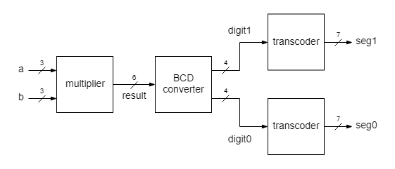
This project comprises a top module with 4 blocks. The first block, multiplier, takes in two 3 bit numbers, a and b, and delivers the result of their multiplication in binary format. The input operands and the result are treated as unsigned integers (natural numbers). The next block, BCD converter, converts the result from the binary format to the decimal. The decimal digits are coded in binary, therefore a multidigit number is coded in the so called BCD format (Binary-coded decimal), where each decimal digit is represented as a 4 bit number.
- create a new project in a new folder
- create a new sorce file for the top module, which is described structurally
- create a new source file for the multiplier. The multiplier is described behaviorally using a continuous assignment.
- copy from the folder of Exercise 1 or Exercice 2 the source file of the transcoder module into the folder of this project. Add the file to the project.
- create a new source file for the BCD converter. Use a behavioral description with integer division operators (/ and %). The quotient will be the first digit value (the digit of tens), the remainder will be the last digit (the digit of units).
- assign switches SW[9], SW[8] and SW[7] for the input a, SW[2], SW[1] and SW[0] for the input b, Digit0 pins for seg0, and Digit1 pins for seg1
- implement and check that the result of multiplying two 3 bit numbers is correctly displayed on two digits in decimal format. If the result is smaller than ten, the first digit will show a leading 0)


