Automata
The automaton is a sequential circuit, used to program a sequence of operations. An automaton is defined by the following elements:
- a set of input values (which for the circuits are input ports);
- a set of output values (which for the circuits are output ports);
- a lot of states that alternate over time and only one of which is active at a given time (which is stored in an internal register for the circuits);
- a state transition function, which calculates the next state of the automaton according to the current status and the input values (which for the circuits is a combination module);
- an output transition function that calculates the next output value, depending on the current state (for Moore type machines), or the current state and input values (for Mealy machines) (which for circuits is a combination module).
At each clock queue, the machine translates to the next state, calculated by the combined logic circuit.
Remark: The total number of states available to an automaton is given by the number of the status register bits.
Remark: There are state coding modes that allow for safe transition in the case of asynchronous inputs. Fortunately, modern synthesis programs automatically detect these cases and recodify the corresponding states.
The interface of an automaton
The interface of an automaton is composed of the following ports:
- the clock signal as input;
- the reset signal as input;
- a number of inputs with different functions;
- a number of outputs with different functions;
Rule: When the reset is active, the machine switches to one of the states, which is the initial state.
Implementing a machine
The implementation part of an automaton is composed of the definition of a state register on a sufficient number of bits to be able to encode the number of states desired, and the definition of states and output transitions implemented by a block ' always' sequentially and a sub-block case.
Note: If the machine reaches an undefined state, then the following transition is in a defective state as a state of error, or in the initial state, as the case may be. The undefined states are those in the block case that are treated by the default condition.
Example
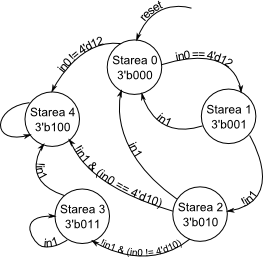
For example, the machine described in the diagram of the following figure, where the output is even the state code:
The code describing the machine is the following:
`define STATE_0 3'b000
'define STATE_1 3'b001
`define STATE_2 3'b010
'define STATE_3 3'b011
`define STATE_4 3'b100

module TestFSM (
        output [2:0] out,
        input  [3:0] in0,
        input in1,
        input clock,
        input reset
);

reg [2: 0] state;

always @ (posedge clock) begin
    if (reset) begin
        state <= `STATE_0;
    end else begin

    case (state)
        `STATE_0: begin
             if (in0 == 4'd12) begin
                  state <= `STATE_1;
             end else begin
                  state <= `STATE_4;
             end
         end

        `STATE_1: begin
             if (in1) begin
                  state <= `STATE_0;
             end else begin
                  state <= `STATE_2;
             end
         end

         `STATE_2: begin
             if (in1) begin
                  state <= `STATE_0;
             end else if (in0 == 4'd10) begin
                  state <= `STATE_4;
             end else begin
                 state <= `STATE_3;
             end
         end

         `STATE_3: begin
             if (! in1) begin
                 state <= `STATE_4;
             end
         end

         `STATE_4: begin
             state <= `STATE_4;
         end

         default: begin
             state <= `STATE_0;
         end
    endcase
end
end

assign out = state;

endmodule

