DIC Seminar 2
Behavioral description, continuous assignment, conditional instructions, use of blocks always for describing combinational circuits.
In the previous seminar the circuits were described through their scheme. In this seminar you will learn other ways of describing combinational circuits, starting from the circuit function.
Keywords: conditional assignment, process, list of sensitivities
Verilog syntax: assign , always , if , case
Verilog is an HDL, a hardware description language, and it's called characteristics that derive from the fact that the language is intended for describing, simulating and synthesizing circuits (rather than executing algorithms). Thus, some instructions like assign and always describe (represent) 'processes that run in parallel. With their help, the behavior of circuits whose output changes as many times as a change of input signals occurs can be modeled.
Exercise 1
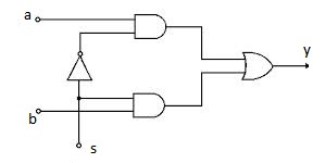
Describe in Verilog a two-input selection circuit (and a selection bit) using:
- assignment statement;
- conditional assignment statement.
Additional explanation
This exercise refers to the circuit described in seminar 1, exercises 1-2. At point 1 the logical expression deduced from the circuit will be used. For point 2, we directly describe the function that this circuit performs: if s == 1, y=b, and if s == 0, y=a.
Exercise 2
Write the selection function of the circuit in the previous example using the 'if' statement. Simulate the operation of the circuit with the implementation of this exercise and exercise 1, point 2.
Additional explanation
To describe a combinational circuit with an 'if' statement, we use blocks 'Always'. Note that in Verilog generally, if statement is used only in blocks' 'always.
Exercise 3
Describe a multiplexer with 4 entries and 2 selection bits using the case statement. Simulate circuit operation.
Additional explanation
Like the if, case statement is used only in a block always; the variables that are assigned must be declared as reg.
Exercise 4
Describe in Verilog a circuit that increments the input (four-bit) number only if the command input is 1.
Exercise 5
Describe a BCD transceiver - 7 segments using the case statement.
The 7-segment binary transceiver has a 4-bit binary number (representing a decimal figure) and calculates at output 7 logical signals that command the 7 segments of a display. IO Device : 7-segment display. For numbers 10-15, we will control the display of the E symbol (for error).
Assignment
- Describe the function of a comparator using the assign statement or the if:
- for two 1-bit inputs and an output that is active when the inputs are equal;
- for two 3-bit inputs, with an output that is active when the inputs are equal;
- for two 3-bit inputs, with three outputs indicating the three cases.
- Describe a 2-bit selection multiplex using
- conditional assignment statement;
- assign statement and logical expressions.
- Change example 5, assuming the input is a hexadecimal digit. Note: There will be no error (E) for the values 9-15 on the input, but the corresponding figures in the base 16, symbolized with A, b, C, d, E, F. '
- Describe in Verilog a schematic that contains the incremental circuit (of example 4) and the binary transceiver - 7 segments (of example 5). Simulate the operation of this circuit.
The main concepts of Verilog introduced in this seminar
Continuous assignment
The continuous assignment from Verilog, the 'assign' statement, is evaluated when the value of an argument changes.
For example, expression
assign a=b + c;
is calculated again if b or c changes its value. The continuous assignment is intended to describe the operation of the combinational circuits, in which the output follows the input changes. All assign instructions run in parallel, as all components of a circuit work at the same time.
Condition assignment
The conditional assignment instruction has the form
assign w=x? a: b;
Assignment depends on the value of x: if x == 1, w=a, and for x == 0, w=b.
Instruction if
The 'if instruction in Verilog has the form
if (condition) ...... //for example, if (a == b)
    else ....;
Assignments in a construct of this type are sequential (not use assign) and require us to declare those variables that change their value, such as reg. Several instructions can be grouped into blocks using begin .... end. To describe a combinational circuit with an if statement, we use the block always. Note that in Verilog generally, the' if 'statement is used only in blocks always.
Processes always
In Verilog, the always statement describes a process that is executed when at least one signal from the list of sensitivities changes (the list of signals that appears in parentheses after the @ symbol).
always @ (a or b or c) //here is not put ";"
    y=a + b + c; //Because of the always block, the sequential assignment is
                   //recalculates each time it changes
                   //one of the signals a, b or c
                   //Attention! y is type reg
More simply, we can write
always @ (*)
Where the notation (*) denotes any change.
When simulating a circuit, all blocks are always running in parallel.
The case block
The Verilog case instruction has the following format:
case (case_expression)
value1: instruction1; /* for different expression values different instr * /
...
default: instruction; /* default case for values not specified * /
endcase
Like the if, case statement is used only in a block always; the variables that are assigned must be declared as reg.
Rules of Good Practice
- When describing combinational circuits, the if statement is specified elsewhere, even if nothing happens. E.g:
a_lt_b = 0;
if (a<b) a_lt_b = 1;
    else ;
For case we will always write the default case, even if we have specified all the possible binary configurations (this is done if the value of the expression is not known, or otherwise it has the "value" x).
