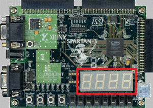
IO Device: Segment 7 segment display
The 7-segment display is used to display numeric (or even alphanumeric) values in natural format, rather than in binary, using the LEDs.
Segment Control
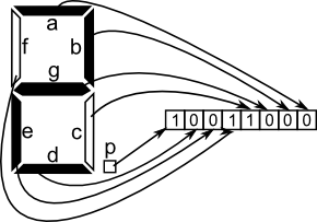
Attention: The 7-segment display control is controlled separately by each segment. Control is done on negative logic, so when the value 0 is propagated to the pin corresponding to a segment, it is lit and when the pin is 1, the segment is off. An example of a control sequence that will illuminate the figure 2 is shown in the figure:
Thus, we will need a circuit with an 8-bit output that will represent the control code for the desired value, which will represent the number we want to see displayed:
- for the desired value 0, the control code will be 8'b10000100 (all segments lit, except the middle and the dot);
- for the desired value 1, the control code will be 8'b11110101 (the right-hand segments lit, the remainder off);
- for the desired value 2, the control code will be 8'b10011000 (see previous figure);
- ... etc.
These values depend on the convention chosen for bit-segment correspondence. For the example above, the order of segments is PDEFCGBA (bit 7 corresponds to the point, bit 6 corresponds to segment D, etc.). Any other permutation of segments is correct, provided the order in the segment control module is reflected in the "Implementation Constraints File".
Caution: The pins to which the segments are linked are written on the development board on the drawing above the display (for Nexys 2, they have the same names as those on the above drawing).
Number control
Segment control is common to all 4 digits available on the board. This means that all segments in the same position in all four digits are linked to the same pin (ie, all active figures at a given point in time will display the same value). Turning on or off a digit is also done on logic denied using pins bound to AN3-AN0 devices. Therefore, the module that controls the 7-segment display will have, besides the 8-bit output needed to control the segments, another 4-bit output that will control the status of each digit (on or off).
Implementing the control circuit
The usual implementation for the control circuit is with a ROM memory.

