Sequential Circuits
Sequential circuits are circuits that are synchronized by a clock signal, ie whose outputs change only on the positive (or negative, clockwise) front of the clock.
Clock signal
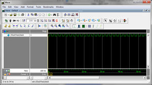
The clock signal is a periodic signal that oscillates with a certain frequency, called the clock frequency.
Note: See syntax Verilog to find out how to generate a clock signal in simulation.
Memory Circuits. Register
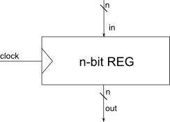
The register is the basic memory cell and the base of the sequential circuits. Once a value is loaded into a registry, it is retained until it is overwritten with another value.
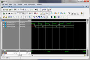
This is the implementation in Verilog of a 4-bit register that only loads the register with the input value, and in the picture you can see a Modelsim simulation that shows that the output only changes on the positive clock front following the change of input:
module Register (
    output reg [3: 0] out,
    input [3: 0] in,
    input clock
)

always @ (posedge clock) begin
    out <= in;
end

endmodule
Reset for sequential circuits
There are situations where registers need to be reset, that is, loaded with a default value. This reset process is typically used when the circuit blocks, for one reason or another, or when it is to be restarted from an initial state. Circuits for which it is necessary to be reset can be added to a reset signal. The description in Verilog of a 4-bit register with a reset signal, which only loads with an input value, is the following:
module Register (
    output reg [3: 0] out,
    input [3: 0] in,
    input clock,
    input reset
)

always @ (posedge clock) begin
    if (reset) begin
        out <= 4'b0;
    end else begin
        out <= in;
    end
end

endmodule
This type of reset is called synchronous reset, because it is only evaluated on the clock front (synchronous with the clock). There are also cases where the reset is asynchronous, and then the active reset queue must appear in the block's list of sensitivities always.


