The Frequency Divider
Some applications need a clock signal with a lower frequency than the main clock of a circuit (this is the 50MHz oscillator on the board development with FPGA). Frequency and period of a signal are inversely proportional (f = 1 / T), so half-frequency implies doubling the period. A 50MHz signal has a 20ns period.
As seen in Laboratory 3, the simplest divider is a counter. But this implementation has limitations. Each bit has a frequency twice as low as the previous bit, so there is a discreet set of possible frequency values that this implementation can provide. For example, for the 50MHz clock, the possible output values are: 25MHz, 12.5MHz, 6.25MHz, 3.125MHz, 1.5625MHz, etc. If we want a clock signal with the 1Hz frequency, this deployment can not provide it.
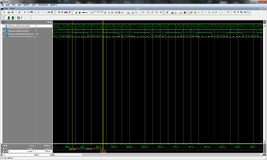
To solve this requirement, a numerator will be used, but otherwise. Instead of insulating a bit to be used as a clock signal, the counter will be given a counting limit value, and when that value is reached, the counter negates the output clock signal according to the waveforms of figure. Therefore, if the clock time of the counter is Tc , then the counter will increment at each Tc time units (each clock queue), meaning that it will reach the limit value, denoted n after 'n * Tc' 'time units. The delay of a clock input from the output register also introduces a clock period, therefore the output signal changes after each (n + 1) * Tc time units. Thus, the period of the output signal is given by changing it twice (0 -> 1, 1 -> 0), a change that lasts up to two complete counts up to the 'n' limit. So, the output signal is 'Tn = 2 * (n + 1) * Tc'. Passing in frequency, fn = fc / (2 * (n + 1)) , where n is the limit value given to the counter.
It can be noticed that this implementation can not generate any output frequency, but the set of possible values is higher than the previous set.
Interface
The frequency divider interface will contain the following signals:
- clock signal and reset signal as inputs (being a sequential circuit);
- limit value given as input (the bit number for this input is specified taking into account the maximum limit value that can be given in the current application);
- clock divided clock, given as output of the circuit.
Implementation
The implementation of this circuit is done using an internal register for counting (with bit size equal to the port for the limit value - the counter must be able to reach the limit value), and a register for the divided clock signal output. The counting register increments until it reaches the limit value, in which case its value becomes 0, and the output register value is 0.
