Applications 2
De la WikiLabs
Exercise 1
design source file for the 1 bit adder
- New Verilog HDL File
- module moduleName endmodule
- module pins: input and output
- multibit vectors [msb:lsb]
- behavioral description with assign
testbench source file for the adder
- New Verilog HDL File
- module moduleName_tb endmodule
- the testbench module has no pins!
- declare logic variables reg varName
- wire declarations, mandatory for multibit outputs
- instantiation moduleName instanceName Usualy, the top-level design module instantiated in the testbench is named dut (device under test)
- connections connect testbench variables to instance pins: .modulePin(varName)
generate stimuli for dut inside the testbench
- initial
- begin/end if more than one instruction in a block
- assignments varName=value
- literals, decimal literals, binary literals
- delay #delayValue
Exercise 2
design source file for the 2 by 2 bit multiplier
- operators in expressions
testbench source file for the 2 by 2 bit multiplier
- control instructions: repeat (nrOfIterations)
- parallel initial blocks
Exercise 3
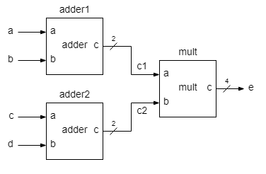
design source file for top-level entity Multilevel hierarchy. Mixed description: top-level - structural description, low-level - behavioral description.
- same module type, different instance names
- internal wires for interinstance connections
testbench source file for the top-level entity
- concatenation operator {varName1, varName2, ...}
- $monitor(%b...,varName1,...)
- format specifiers %b for binary (logic) values, %d for decimal values


